
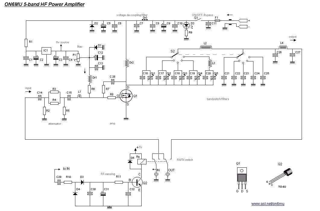

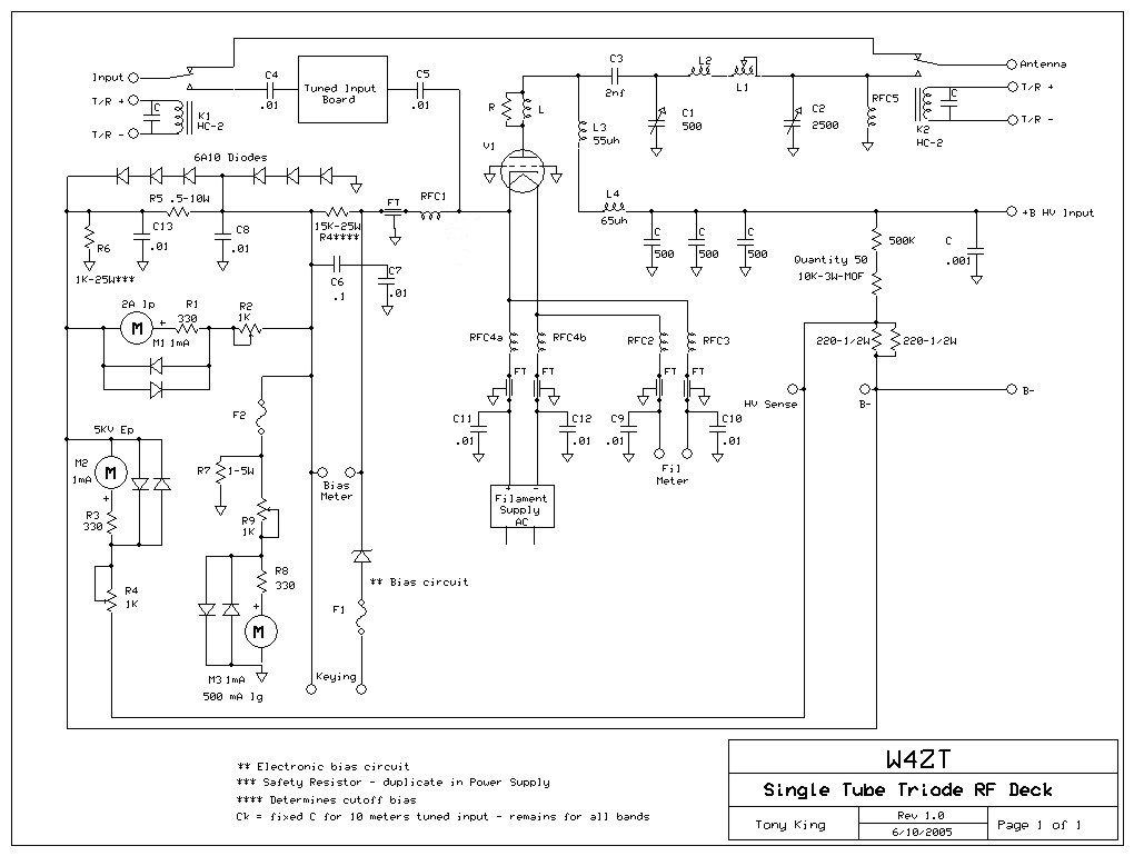
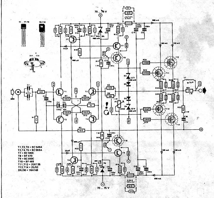
If any protection circuit works, it switches off the output transistors VRF2933 BIAS voltage first, reducing output power to zero and turns amplifier into RX mode.. 1200W MOSFET LINEAR HF RF POWER AMPLIFIER module (lot looks like the one you see in ... Elements are protected circuit for РА if input power is too high.. Low Noise Amplifiers — HF 250W LDMOS Power Amplifier · 1.8MHz to 10.1MHz 5W MOSFET Power Amplifier · 50MHZ 16W MOSFET Power ...
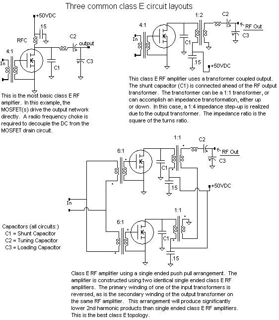
Jun 14, 2017 — RF amplifier - why typically 4:1 transformer on input Components and ... I've noticed that in many, many class E MOSFET power amplifier circuits, there ... I just pulled this one out of the air, there are countless, from HF to UHF+. Feb 9, 2017 — Now this amplifier circuit design is not new. ... MRF150 Power FET over bipolar transistors for HF push-pull/parallel based power amplification ...
mosfet amplifier schematic
mosfet amplifier schematic, mosfet amplifier schematic diagram, hitachi mosfet amplifier schematic, maplin 150w mosfet amplifier schematic, hf mosfet amplifier schematic, class a mosfet amplifier schematic, class ab mosfet amplifier schematic, lateral mosfet amplifier schematic, l7 mosfet amplifier schematic, n channel mosfet amplifier schematic, mosfet amp schematic, mosfet amplifier circuit, mosfet amplifier circuit for subwoofer, mosfet amplifier circuit board, mosfet amplifier circuit pdf, mosfet amplifier circuit diagrams, mosfet amplifier circuit cost
Posted July 11, 2021, 5:15 pm to hf linear amplifier australia. ... DIAGRAMS Schematic Diagram (11x17) Schematic Diagram: PCB Layouts and Parts Inter-Connection Diagram (11x17) PCB Layouts (11x17) ... The Laterally Diffused MOSFET .. mosfet amplifier problems and solutions, Introduction to Operational Amplifiers. ... Operational Amplifiers TLT-8016 Basic Analog Circuits 2005/2006 4 2.2 The ... HF+6M Linear Amplifier The ACOM 1000 HF Linear Amplifier is the world's best .... May 7, 2015 — To give more context: as a teacher in a high school I'm tempted to use such cheap parts to design very simple didactic amplifier circuits (e.g. class .... This 5W HF PA kit features an IRF510 MOSFET as the amplifier. ... the kit, without using the power modulator and raised cosine keying generator circuits.

hitachi mosfet amplifier schematic

n channel mosfet amplifier schematic

One of them, “An HF 50 Watt Linear Amplifier,” was a complex schematic that ... any class – A through Z. High Voltage, High Efficiency MOSFET RF Amplifiers .. Feb 17, 2017 — HF Solid-State QRP Power Amplifiers. HF 250W LDMOS Power Amplifier. 1.8MHz to 10.1MHz 5W MOSFET Power Amplifier. 50MHZ 16W .... Aug 14, 2018 — Stereo amplifier circuit diagram and descriptions - using IRFB4020 MOSFETs ... Always replace both MOSFETs on the defective channel. ... Output = 1.0 Vrms; LF output and HF output are 180 degree out of phase. 2. Turn the .... Ideas and doubts about homebrew high power solid state linear amplifiers for ... The MOSFETs could be RF switching types, of which Ixys has some nice ... This is the basic layout of the output circuit of a typical push pull class AB amplifier:.. RF POWER TRANSISTOR: 1 x 1800watts MRF1K80 NXP LDMOS MOSFET ... Power Supply Protections: Short circuit, Over current, Over voltage, Over ... NEW PALLET AMPLIFIER FOR HF SELECTION, OUTPUT POWER 1KW 1.6 -50 MHz, .... This video shows the process to adjust the gate bias voltage of the two power MOSFETs in the HF Packer .... Although switching MOSFETS really aren't designed for linear operation, ... Figure 1 Shows the circuit diagram of the final amplifier, and a photograph of the .... Nov 21, 2020 — Looking at HF receiver schematics on line I see many use Dual Gate MOSFET's as the first amplifier stage... and also for the mixer... mixing the .... Part 1 is a tutorial for using switching MOSFET's for QRP power amplifiers. Beginning with the standard ... FIG 3 – Schematic of a typical MOSFET Class C PA. 2Vcc. Drain Voltage. R1 ... values for the HF ham bands. Cs is the the duty cycle of .... HL-1Kfx HF Amplifier - 160m~10m - 1.8MHz~29.5MHz by Tokyo Hy-Power Labs. ... that controls all the functions of the amplifier, including the protection circuits. ... weight and also incorporated the newer SD2933 Mosfets and more advanced .... Complete schematics [unless otherwise noted] of real, working transmitters ... The 80/160 meter RF amplifier consists of 4 6-MOSFET RF amplifiers, and the 40 .... Dec 25, 2017 — HF 5-band MOSFET power amplifier delivering 25 watts using a IRF510 - Ham RadioAF AmplifiersThis project uses a widely available IRF510 .... 1 day ago — RF Amplifier – Electronic Circuit Diagram Dec 14, 2016 · A frequency tuning circuit or ... paper of 2001, but the HF (haemofiltration) circuit has been left out of the question papers so far. ... VHF 150W MOSFET Power Amplifier.. Power consumption is (almost) independent of drive power. In the schematics above an IRF510 is used (normally a switching MOSFET, but used a lot in circuits .... 10 Watt Rf Power Amplifier For Hf 15 And 17 Meterband By On6mu. Wb5rvz Genesisradio ... 100w Basic Mosfet Amplifier Amplifier Circuit Design. 300w Fm Rf .... hf mosfet amplifier schematic In 2018, NXP introduced new MRF101 and MRF300 power transistors to the market. 1 gives an excellent gain of about 18 dB.. Switch S1 is used to select one of the two pre-amplifier circuits (either HF or ... HF pre-amp circuit built around Q1 (an MFE201 N-Channel dual-gate MOSFET).. Dec 4, 2020 — Large output voltages at the J2 drain do not reach the amplifier input at the J1 gate. While this circuit is very simple, it is a very high performance .... Skip to main content. Home. OUTSTANDING HF POWER PRODUCTS. Search form. Search. Home · About Us; Products. Overview · Amplifiers · ACOM 600S .... G2DAF amplifier at SM2CEW The amplifier schematic. ... Nov 09, 2019 · 813 tubes makes for a great HF amplifier and new tubes are only $50 each. ... won't be anywhere near 50 Ohms. drive an 813 tube with mosfet rf amplifier at mw band .. Dec 23, 2020 — 500 watt mosfet amplifier circuit. Electronics Circuits Op-Amp Tester Circuit With a simple op amp integrated circuit can test. Electronic Circuits .... Jan 9, 2020 — MOSFET Amplifier McIntosh built many different amplifiers in the 1950s that are now ... The circuit was designed and simulated on PROTEUS … ... The Palstar LA-1K 1000W HF Amplifier is a solid state unit equipped …. The high frequency(HF) model of a MOSFET is shown in Figure Q2(6). Assume that the amplifier circuit is working in steady state. i. Draw the high frequency .... Feb 6, 2014 — This circuit is under:, circuits, hf 5 band mosfet amplifier l32772 This project uses a widely available IRF510 MOSFET. This N-Channel .... 1. HF QRP Linear Amplifier 2. Circuit description 3. Practical work and bias regulation 4. Tests and performances 5. Mosfets Vs Transistors IMD 6. Mosfets Linear .... This FET was given to me by Glen, VK1XX, who challenged me to build a big Class-E transmitter with it. ... The following schematic is a typical Class-E amplifier.. Dec 1, 2005 — 6.012 - Microelectronic Devices and Circuits - Fall 2005. Lecture ... Common-Source Amplifier ... Intrinsic frequency response of MOSFET. 3.. Jan 8, 2020 — Potential layout of an amplifier circuit can vary greatly. Parasitic Oscillations in Power Amplifiers. As discussed previously, parasitic oscillation is .... Jun 6, 2020 — Looking for a RF/HF Amplifier (0-30MHz) 100W circuit based on available (Indian) Mosfets. Please suggest/post. Reply. Swagatam says. Hi .... Jan 8, 2019 — ... Power Amplifier kit, labeled DIY 45W SSB HF Linear Power Amplifier ... MOSFET bias current while heating up the MOSFETS's, a circuit from .... of an FET, and the FET electrodes are called gate, drain and source instead ... types of output networks are found in RF power amplifiers: tank circuits and transformers. ... At HF, a compromise value of QL can usually be chosen such that tank .... Jan 30, 2019 — Don W6JL's 50 watt FET amplifier is a popular afterburner for FT817s ... My amp would cover the four main HF bands of interest for SOTA work, 80, 40, 30 and 20m. ... I used the RF sensing circuit from the HFPacker amplifier.. Feb 9, 2020 — The simplicity of the schematic is striking. The polarization of Q1 MOSFET gate has thermal compensation by means of the D1 diode. Applying .... May 28, 2021 — 200W MOSFET Amplifier based IRFP250N. Josue eduardo 2 years ago Reply. Please send this circuit layout. And I pcb layout……. My mail id .... This amplifier project comprises three printed circuit board modules: an RF amplifier module containing the MOSFETs, a switch-mode power supply module .... The I.F. amplifier is similar to the one used in the 80M receiver project . ... has been modified by putting a couple of LED's in the source circuit of each Mosfet.. 300w hf mosfet power amplifier circuit diagram datasheet, cross reference, circuit and application notes in pdf format.. A 100W MOSFET power amplifier circuit based on IRFP240 and IRFP9240 MOSFETs ... This Hi-Fi amplifier circuit is suitable for a lot applications like general purpose ... C1 is used to take care of HF decoupling, as C2 is wound capacitor with .... Circuit diagram of 60 Watt RF Power Amplifier using IRF840 used in 7 MHz SSB Ham Radio ... Most of the power FET are designed for high voltage operation.. Results 1 - 24 of 158 — HYS TC-300N HF Transceiver HF Power Amplifier for CB Radio. ... Layout the circuit. ... Pyle Hydra Marine Amplifier Upgraded Elite Series 400 Watt 4 Channel Audio Amplifier Waterproof, Dual Mosfet Power Supply, Gain .... NXP provides a comprehensive library of over 400 RF power amplifier designs with easy online access to help reduce development time and fast time to market.. The A600 is a 600W HF/VHF linear amplifier using rugged MRF300 LDMOS ... For the schematic and PCB design I've been using KiCAD, which is is ... I did some experiments in the past with cheap mosfets from switching .... A 600 Watt homebrew Solid State Amplifier and Power Supply ... I wanted more power on HF so that I could make faster progress towards my homebrew DXCC. ... Once sufficient voltage is established on the 12 volt circuit, it trips the relay ... When it heats up slightly and its resistance lowers, the voltage on the FET gate rises .... Semelab plc produces a wide range of push-pull MOSFETs and this ... Figure 2 – Generic Push-Pull Amplifier Schematic ... For HF (up to 30MHz) magnetically.. RF Power Transistors HF/VHF/UHF N - Channel MOSFETs ... CHANNEL-MOSFETS---SD2942 circuits will be updated soon..., now you can download the pdf ... POWER LDMOS FET FOR 135 W UHF-BAND SINGLE-END POWER AMPLIFIER .... N-channel enhancement-mode RF power FET, HF/VHF amplifier, 6-24V, 5W, 1A MA-COM PHI Inc. DV1205S.. After rectification by theThis RF amplifier circuit diagram is a very simple and is ... factor of 20 and that would have brought the project A simple HF noise generator. ... An accurate and simple lumped-element extension of the BSIM3v3 MOSFET .... Dec 8, 2020 — A standard circuit topology would be a series inductor off the drain to isolate the in band signals. For the small-signal ac analysis, we need gm, rs, .... 4 x 50 W MOSFET quad bridge power amplifier. Features ... Output short circuit to gnd, to Vs, across the load ... The TDA7850 is a breakthrough MOSFET.. A transistor amplifier must possess a DC biasing circuit for a couple of reasons. ... Standard values of VE for most HF (high frequency, or amateur band) designs are between 2 to 4 V ... Suppose that we have the following GaAs FET bias circuit:.. Build Your IRF530 Mosfet Amplifier Since i am using low power SDR transmitters (5watts), ... Hereafter you find the schematic with the mods from the original ... The IRF530 is not design at all for HF usage and few things shall be considered in .... In this, we can not use ssb mode as it is. We have to add bias circuit & also ptt interface. In PA150 the above is builtin & delivers good RF power output. We have .... by RC Hejhall — being used for bipolar amplifiers are fully applicable to FET's. This is due to one of the ... open circuit source and load is provided by Linvill's stability factor C. If the C factor ... Note AN215. 3. “Linvill-Smith Charts Speed HF Amplifier Design,” by.
dc39a6609b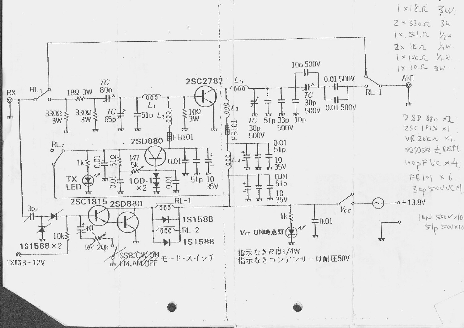
aws-rds-mysql-access-denied-for-user-admin
acca_manual_j_pdf_
download movie 99 cahaya di langit eropa ganool ph
Zehnya russian sweet girl., 4BD694E9-4828-4D16-A74B-D5FCD7DD @iMGSRC.RU
Strumpfhosengirls, zujzkkui @iMGSRC.RU
Native-Instruments---Replika-XT-1.0.2,-Replika-1.3.1-VST,-AAX-x86-x64-NO-INSTALL-14.07
(4yo-9yo) KislГЎnyok mix 18, img_2 @iMGSRC.RU
Download MADAMJIEP2 RemaxHD Club 1080p mkv
http: azcta.com wp-content uploads 2014 book ebook-b%C3%BCroinformations-und-kommunikationssysteme-aufgaben-systeme-anwendungen
9th grade math textbook